

Around this time last year, SparkFun worked with a team from SketchUp to design and build a Corn Hole game with an integrated LED score counter. This design made its debut at the 2016 SketchUp Basecamp Conference in Steamboat Springs, CO. A designer on their team, Eric Schimelpfenig, asked if we wanted to work on this project together. He'd do the 3D design of the Corn Hole tables, and SparkFun would integrate the electronics.

This year, SketchUp approached SparkFun with another opportunity to collaborate. Eric's idea was to illustrate just how easy it is
Concept Drawing
The concept is based loosely on the idea of building a SketchUp MAME (Multi-Arcade Machine Emulator) cabinet that has buttons and lighting effects controlled by an Arduino. The heart of the machine is a simple tower PC, and the center screen is a standard 27" computer monitor. Arcade buttons would be integrated into the system using a 32u4 based Arduino to inject keystrokes to the computer to mimic the use of hot keys.

Again, Eric took care of all the mechanical design. The electronics integration and programming fell to us at SparkFun. Here are the parts that I used:
- 1 Pro Micro
- 1 Multiplexer Breakout Board - 8 Channel
- 1 WAV Trigger Board
- 10 Arcade Buttons
- 2 Flush-Mounted Metal Buttons
- 1 Big Red Dome Button
- 1 5m strip of WS2812 LEDs
- 2 Beefcake Relay Modules
- 3 Female Header Pins
- Terminal strips (Amazon)
- 2.8 x 0.5mm Spade Crimp Connector (Amazon)
- 0.25 in Spade Crimp Connector (Amazon)
- SATA15 Power Cable Adapter (Amazon)

If you've never used SketchUp before, it's a tool that makes it easy to learn 3D design and CAD (Computer Aided Design). SketchUp has a great series of getting started videos here. When you open SketchUp, you'll see a set of basic drawing tools along the top of the window.
The drawing tools are easy enough to find and click on with a mouse, but as most proficient users of SketchUp know, it's much easier to use hot keys (or keyboard shortcuts) to switch between these tools. The hot keys in SketchUp are fairly easy to remember ('l' for line, 'r' for rectangle, 'c' for circle, 'e' for eraser, etc.), but for a novice, it's still one more thing to learn.
So, what we've done with this arcade setup is connect arcade buttons to an Arduino to emulate the key presses for these hot keys. The Arduino Leonardo or any Arduino board with the Atmel 32u4 chip has the ability to connect to your computer as a USB HID (Human Interface Device). This is basically the same thing as a USB keyboard or mouse. So, what we did was create a program to read button presses and inject
In the visual below, you can see the key mapping we implemented.

For fun, Eric asked to have
In the planning stage, we mapped out all of the buttons to
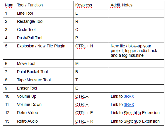
In addition, Eric requested that we trigger an audio track on startup to make the whole experience interesting while you wait for the PC to boot up. We were also asked to add some fun lighting effects throughout the arcade using WS2812 LED strips and to kick off a relay that controls a fog machine when you hit CTRL+N for
The WS2812 LED strips are individually addressable RGB LEDs that require a single signal line from the Arduino. We use these LED strips in a lot of projects here at SparkFun, including the Corn Hole project last year. These LED strips are easily controlled in Arduino using the NeoPixel Library.
For the sound effects, we are using a WAV Trigger Board. This is one of the easiest ways to add sound to a project. Load up an SD card with audio files in WAV format. Name the files starting with "001", "002", "003"... to connect these audio files to the trigger pins on the board. When these pins are grounded, the respective file will play. The WAV Trigger Board can play up to 14 tracks simultaneously. It's a pretty neat board. When wiring this up, make sure that you have a common ground across all circuits.
Here are the big-picture concepts for the electronics design:
- 13 push buttons will inject keystrokes into the computer running SketchUp via USB HID control using an Arduino — 13 control pins.
- 2 control pins will trigger sound effects using the WAV Trigger Board for the boot-up sound effect and the self-destruction sound effect when the center "bomb" button is pressed.
- 2 control pins for the
Beefcake relays to control the fog machine. Eric asked for the main power on the fog machine to be controlled because it draws a lot whenrun continuously. So, we'll need two relay controls. One for the fan and one for the mainpower. - 1 signal control pin for the 2x WS2812 LED strips will be on the front of the arcade (~26" each).
- 1 signal control pin for the 2x WS2812 LED strips will be on the sides of the arcade (~44" each).
- 1 control pin for the LEDs on the center Big Dome button and the Volume Buttons to be lit and controlled.
Total I/O pins required: 20
These all seemed simple enough, but I wanted to break it down into a few simple prototype projects. The first was to just integrate button presses into keystrokes on the computer.
Initial Prototype (v0.1)
Initially, I started the project using a standard Arduino Leonardo, but the keyboard library was exhibiting mysterious issues that I couldn't resolve. Thankfully, I found that the SparkFun Pro Micro worked as expected. The Pro Micro, however, has
This prototype was really short and simple. I just wanted to make sure I could get button presses sending keystrokes through the Arduino to the computer through the HID control. I grabbed three buttons that I had on my desk, a mini breadboard and a Pro Micro, and threw together a really quick, rough sketch to test this out.
I wanted to keep the wiring simple, so I am not using pull-up resistors with these buttons. We are going to use the INPUT_PULLUP pinMode to set the internal pull-up resistor in Arduino.

Test Code - v0.1
This test code was thrown together pretty quickly, and it wasn't written to be scalable. I just wanted to read button presses and send keystrokes.
Here's a quick video showing an early test with just three buttons that I sent over to SketchUp to show what we could do. Remember, the code wasn't written to be scalable, but it shows that buttons are controlling the functions in SketchUp.
Prototype v0.2

Now that I had it working with a few buttons, I wanted to see if I could add more buttons and test the combination
Using the Pro Micro and 6x 12 mm button switches, I built this simple test circuit. This is the most number of buttons that will fit on a half-size breadboard. If you want space for more, you can add a second half-size breadboard or just use a larger full-size breadboard. For the purposes of this test, six buttons would be perfect.
Test Code v0.2
This time, I wanted the code to be scalable. So, to do this, I have an array
With a focus on scalability, I am using a for() loop to cycle through to check each button pin and then command the keypresses. The Keyboard.releaseAll() method resets the keyboard and releases all of the "press" commands.
Prototype v0.3 - Build This One at Home!
I now had the bulk of the coding done, but I really wanted to have a physical construction of the buttons to test with. I also wanted to integrate both the volume controls and the bomb button (CTRL+N) controls. I simply scaled the code from the v0.2 prototype to include 11 buttons, laser cut a cardboard enclosure, mounted the 11 buttons, and wired it all together.

The template for the cutting file is here as SVG and PDF. I daisy chained the ground wires for all the arcade buttons together using 0.25" Female Spade Crimp Connectors. The inset metal volume buttons use a smaller spade connector that is 2.8mm x 0.5mm. I ran these 12 connections (11 for the buttons and one for the button LEDs) to a Pro Micro. To keep the wiring straight, I connected the buttons from left to right sequentially to the pins on the Pro Micro.
This design is ready for you to build at home and automate your own SketchUp experience! Or, adjust the code to match the hot keys for your favorite game or other drawing tools. It's all open source and available for you to hack on!
Test Code v0.3
This code is essentially the same as v0.2, except we added extra pins and keystrokes for the extra buttons.
Here's a demo of the project running. In this video, I have the first four SketchUp tools connected, the two volume buttons, and the "bomb" CTRL+N button.
Now that I've done the hard part, I need to find a way to get more pins.
How to Get More Pins! Multiplexing Pins
The Pro Micro has 16 pins exposed (eight on each side, not including TX and RX). To read the 13 buttons, control two relays, drive two different LED strips, trigger two sound effects and light up the button LEDs, I'm going to need at least 20 pins.
One way to access more pins is to use a device called a multiplexer. A multiplexer is one of the basic digital circuit elements that is taught in an introduction to digital electronics course. It takes multiple inputs and routes them to a single output based on the inputs to one or more selection pins. We are using an 8-to-1 Multiplexer breakout board based on the 74HC4051 chipset. It has three selection pins (S2, S1 and S0), one output pin (Z) and eight input pins (Y7–Y0). Using this, we can read eight buttons with only four I/O pins on the Pro Micro. With the Pro Micro, I'm short four pins. The multiplexer gives me these four extra pins back.
The three select pins (S2, S1, S0) are used to select which of the inputs are read. It works using a simple binary selection: 000 selects Y0, 001 selects Y1, 010 selects Y2...and so on. We simply moved the six buttons from our first prototype to this breakout board and tested some new code.

Test Code v0.31
This test code just tests to see if the button presses are being read
When you upload this code, open up the serial monitor, and you should see the button presses being read
New Wiring Configuration
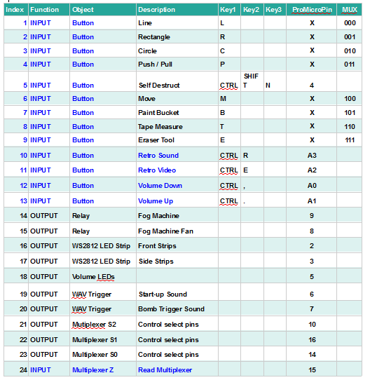
Now, with the multiplexer, I had to re-configure the pin assignments and configuration for the Pro Micro. What I did was connect the main controls for the SketchUp tools directly to the multiplexer. The eight main SketchUp tool buttons are connected to the multiplexer. I spent a lot of time making sure that the wiring was going to be as clean as possible. The table below shows the pin configurations used:
Final Integration and Assembly
Now that I had all of the bits and pieces tested, it was time for the final electronics board integration and assembly. As I was laying out the components, I discovered a need to securely mount the Pro Micro. So, I made a 3D-printed carrier for the Pro Micro in SketchUp. The model is available
Here is the planned layout of the electronics board. I used these terminal strips to make connecting to the buttons easier. I used this layout to laser cut the mounting holes for all of the parts and wired up the board to ship out to Eric for the final installation. I also used
Relay Control Wiring
To control the main power on the fog machine, I could have used a PowerSwitch Tail, but I wanted this setup to be as generic as possible. So, I used two Beefcake relay modules instead. The Beefcake relay module has a transistor driver circuit built in so that you can control the relays directly from the Arduino. The relay module has three screw terminal outputs: common (COM), normally open (NO) and normally closed (NC). One of the relays would go directly to power the fan for the fog machine. The other would be used to switch on and off the main power to the fog machine itself.
To control main A/C power, I spliced the relay into an extension cord. Similar to wiring a switch for your house, you want to switch the HOT line in A/C. In most wiring, the HOT line is usually black. Neutral is white, and
I stripped away about ⅛" of insulation — just enough so that all of the copper would be covered inside the screw terminal. If there's any exposed copper, you have the risk of a short circuit. And, with A/C power, that can be bad, so cut down the wire to make sure there is no exposed copper. I inserted the HOT side that connects to the wall into the NO terminal and the other side, which goes to the fog machine, to COM terminal. This seemed to be the safest approach. As you can see in the finished wiring, I also added strain relief and zip ties to keep anything from moving around.
Here is what the board looked like when it was completely wired up. I used CAT5 cable for all of the buttons. The WAV Trigger is not shown here, and it isn't wired in yet. There is an extension cord that has been spliced into the Beefcake relay for the fog machine main power control.

Final Code Integration
With the board wired up, I was able to do some final testing and integration of all the elements. I included code to drive the WS2812 LED strips and control the relays for the fog machine. During the startup routine, we trigger the WAV
Each time a button is pressed, all of the LEDs flash. And, when the machine is idle after a certain period of time, the LEDs all start a breathing pattern similar to the lit Apple logo on a Mac.
To do this, we used a variation on the Blink without delay example code to set a timer variable that watches when the machine has been idle for a certain period of time. When the code has detected that the timer has expired, it kicks into the breathing LED code. It's important when reading button presses that you minimize the use of blocking functions like long delays. We used a similar technique in the code to time out for the fog machine, as well.
Finally, when the Dome button (Bomb icon) is pressed, we kick off the fan relay switch for the fog machine. This creates a billowing cloud of fog in front of the arcade machine and resets the SketchUp program.

Completed Cabinet and Installation
Eric did a tremendous job with the mechanical design and fabrication of the arcade. The finish and polish


Final Demo
After Eric fully installed the electronics, we tweaked the code to match the timing of the audio clips and filmed a demo of the completed project. Check it out here:
Questions? Comments? We'd love to hear from you!
Maker Education, programming