
A few teachers have recently asked me about ways to engage students with digital fabrication tools like the 3D printer and laser cutter. Many schools have invested in these tools but the curriculum doesn’t yet integrate them into the syllabus, which is a huge bummer.
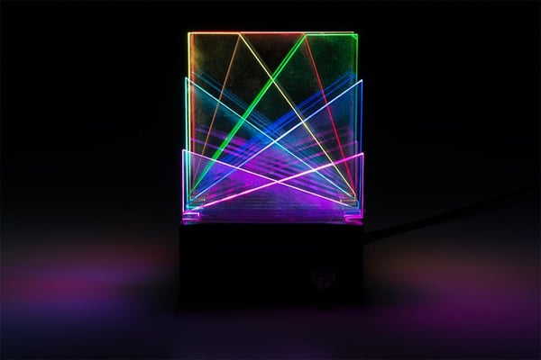
I recently designed a little LED project dubbed the ‘Desktop Light Sculpture’ that relies heavily on digital fabrication. I can absolutely see it playing out nicely in the classroom as a group project. It features a 3D printed base enclosure housing a small programmable electronics circuit and laser etched acrylic inserts.

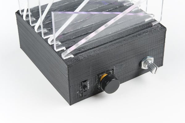
The way the sculpture works is pretty simple. Hidden inside the base is an 8x8 addressable LED matrix divided into rows. When the LEDs are on, they shine directly to the edge of the laser cut inserts, causing them to be ‘edge-lit’. The resulting visual effect is quite beautiful. The light is picked up by any etched part of the acrylic as well as the edges of the plastic form itself. The base enclosure has two layers of slots on top. The first, which is visible from the outside, holds the acrylic inserts snugly in place. The second, which you can see from the inside of the base, separate each row of LEDs from the others to isolate the colored light applied to the acrylic.

I would break this project down into 3 parts that students can work on in groups as well as individually.
PART 1: The 3D Printed Base + Circuit
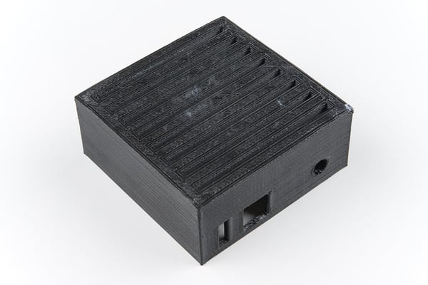
This part of the project is an interesting challenge because students will be designing around the specific dimensions of the electronics and acrylic. They will need to learn how to use a caliper, discover the nature of tolerances, and practice problem solving figuring out how the parts can fit together inside the enclosure, not just on a breadboard.
This will take plenty of prototyping and trial and error. I have no less than 15 test prints from this project on my own desk. In order to save time and filament, I modeled each element of the final enclosure individually to test the dimensions before putting together the complete model. In this vein, this part of the project can absolutely be a group effort. One student can work on figuring out the acrylic slots, the second can figure out how to isolate the light, while the other works on the spaces for the button, switch and potentiometer, etc. This is a great exercise for bringing digital designs into the real world. You can also totally bypass this step by downloading the 3D model which I have posted to thingiverse.
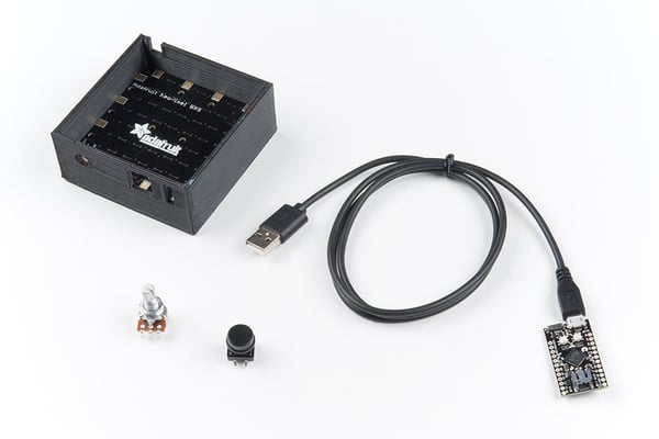
Students will also need to solder their electronics together inside the enclosure. The image below illustrates how the individual electronic components fit together.

All parts included in my example project can be found here.
PART 2: The Laser Cut Inserts
This part of the project allows students to be creatively expressive and individualize their project. The laser cut inserts can be any shape and size, as long as there is a tab to fit into the slot on the base. They can feature any etched design and layer in endless patterns and configurations. Because they are removable and replaceable, each student in a given group can make their own inserts, so that they can feel ownership of the project and invest in the creative exercise. It’s a great way to demonstrate the creative value of electronics!
PART 3: The Program
The LEDs used in this project can be programmed and re-programmed a million times over to feature different colors, patterns, and animations. Each student can work on their own program to create a unique color profile for their design. For example, a project featuring laser cut mountains scapes might use different color LEDs than a project featuring a unicorn. The programming of the LEDs is the final layer of creative expression and is another great way to show students that engineering can be used as a creative tool. The program I wrote for this project can be found below and can be used as a base template for students to build off of. In my example, the switch is used to power the project on or off, the button is used to cycle through different ‘modes’ of LED color design, and the potentiometer is used to control the brightness.
//Desktop light sculpture by Melissa Felderman for SparkFun Electronics
#include <Adafruit_NeoPixel.h> //include adafruit library
#define PIN 6 //LED matrix pin
#define brightPot A0 //potentiometer to control brightness
#define pwrSwitch 4 //power switch
#define momBut 5 //button to control LED mode
int numPix = 64; //total LED count
int brightPotVal; //Variable to hold pot value
int pixelBrightness; //variable to hold brightness value
int switchState; //variable to hold switch value
int butState; //variable to hold button value
int mode = 0; //starting mode for switch state
int prevButState = LOW;
boolean butBool = false;
int topMode = 4; //max number of LED modes in switch state
unsigned long lastDebounceTime = 0;
unsigned long debounceDelay = 200;
Adafruit_NeoPixel strip = Adafruit_NeoPixel(numPix, PIN, NEO_GRB + NEO_KHZ800); //declare neopixel matrix
//create an array for each row of LEDs
int rowOne[] = {0, 1, 2, 3, 4, 5, 6, 7};
int rowTwo[] = {8, 9, 10, 11, 12, 13, 14, 15};
int rowThree[] = {16, 17, 18, 19, 20, 21, 22, 23};
int rowFour[] = {24, 25, 26, 27, 28, 29, 30, 31};
int rowFive[] = {32, 33, 34, 35, 36, 37, 38, 39};
int rowSix[] = {40, 41, 42, 43, 44, 45, 46, 47};
int rowSeven[] = {48, 49, 50, 51, 52, 53, 54, 55};
int rowEight[] = {56, 57, 58, 59, 60, 61, 62, 63};
void setup() {
Serial.begin(9600);
strip.begin();
strip.show();
pinMode(momBut, INPUT);
pinMode(pwrSwitch, INPUT);
}
void loop() {
brightPotVal = analogRead(brightPot);
pixelBrightness = map(brightPotVal, 0, 1023, 0, 200);
switchState = digitalRead(pwrSwitch);
butState = digitalRead(momBut);
strip.setBrightness(pixelBrightness);
strip.show();
//function to debounce button
if ((millis() - lastDebounceTime) > debounceDelay) {
if ((butState == HIGH) && (butBool == false)) {
butBool = true;
mode++;
lastDebounceTime = millis();
} butBool = false;
} if (mode > topMode) {
mode = 0;
}
Serial.println(mode);
//switch state function to cycle through modes on LEDs, you can add as many or as few as you would like
if (switchState == HIGH) {
switch ( mode ) {
case 0:
for (int i = 0; i < numPix; i++) {
strip.setPixelColor(i, 255, 255, 255);
}
strip.show();
break;
case 1:
rainbow();
break;
case 2:
buleGreenGradient();
break;
case 3:
pinkGradient();
break;
case 4:
yellowGradient();
break;
}
} else if (switchState == LOW) {
for (int i = 0; i < numPix; i++) {
strip.setPixelColor(i, 0, 0, 0);
}
strip.show();
}
}
//functions for LED colors
void everyOther() {
for (int i = 0; i < 8; i++) {
strip.setPixelColor(rowOne[i], 255, 255, 255);
strip.setPixelColor(rowThree[i], 255, 255, 255);
strip.setPixelColor(rowFive[i], 255, 255, 255);
strip.setPixelColor(rowSeven[i], 255, 255, 255);
strip.setPixelColor(rowTwo[i], 0, 0, 0);
strip.setPixelColor(rowFour[i], 0, 0, 0);
strip.setPixelColor(rowSix[i], 0, 0, 0);
strip.setPixelColor(rowEight[i], 0, 0, 0);
}
strip.show();
}
void pinkGradient() {
for (int i = 0; i < 8; i++) {
strip.setPixelColor(rowOne[i], 185, 0, 255);
strip.setPixelColor(rowTwo[i], 195, 0, 230);
strip.setPixelColor(rowThree[i], 205, 0, 200);
strip.setPixelColor(rowFour[i], 215, 0, 160);
strip.setPixelColor(rowFive[i], 225, 0, 120);
strip.setPixelColor(rowSix[i], 235, 0, 80);
strip.setPixelColor(rowSeven[i], 245, 0, 40);
strip.setPixelColor(rowEight[i], 255, 0, 10);
}
strip.show();
}
void buleGreenGradient() {
for (int i = 0; i < 8; i++) {
strip.setPixelColor(rowOne[i], 0, 75, 255);
strip.setPixelColor(rowTwo[i], 0, 100, 225);
strip.setPixelColor(rowThree[i], 0, 125, 200);
strip.setPixelColor(rowFour[i], 00, 150, 175);
strip.setPixelColor(rowFive[i], 0, 175, 150);
strip.setPixelColor(rowSix[i], 0, 200, 125);
strip.setPixelColor(rowSeven[i], 0, 225, 100);
<strip.setpixelcolor(roweight[i], 0,="" 255,="" 75);<br=""> }
strip.show();
}
void yellowGradient() {
for (int i = 0; i < 8; i++) {
strip.setPixelColor(rowOne[i], 255, 255, 25);
strip.setPixelColor(rowTwo[i], 255, 220, 25);›
strip.setPixelColor(rowThree[i], 255, 190, 25);
strip.setPixelColor(rowFour[i], 255, 160, 25);
strip.setPixelColor(rowFive[i], 255, 130, 25);
strip.setPixelColor(rowSix[i], 255, 100, 25);
strip.setPixelColor(rowSeven[i], 255, 70, 25);
strip.setPixelColor(rowEight[i], 255, 40, 25);
}
strip.show();
}
void rainbow() {
for (int i = 0; i < 8; i++) {
strip.setPixelColor(rowOne[i], 255, 0, 0);
} for (int i = 0; i < 8; i++) {
strip.setPixelColor(rowTwo[i], 255, 100, 0);
} for (int i = 0; i < 8; i++) {
strip.setPixelColor(rowThree[i], 255, 255, 0);
} for (int i = 0; i < 8; i++) {
strip.setPixelColor(rowFour[i], 0, 255, 0);
} for (int i = 0; i < 8; i++) {
strip.setPixelColor(rowFive[i], 0, 255, 200);
} for (int i = 0; i < 8; i++) {
strip.setPixelColor(rowSix[i], 0, 0, 255);
} for (int i = 0; i < 8; i++) {
strip.setPixelColor(rowSeven[i], 255, 0, 255);
} for (int i = 0; i < 8; i++) {
strip.setPixelColor(rowEight[i], 255, 0, 130);
}
strip.show();
This project has a few drawbacks for the classroom that I want to address. First and foremost, the parts I used in my example are pricey. The project can definitely be scaled down in cost by using a single LED strip or bar instead of the matrix, using one piece of acrylic instead of 8, and using a less expensive microcontroller. Of course this means losing the layering effect of the laser etched acrylic, but a single edge-lit piece is still super cool for students to work with. Most microcontrollers should be compatible with this project, including the micro:bit.
Furthermore, 3D printing is a slow process. It will take hours for a single test print to finish, so time management on this project needs to be considered. This is one of the reasons it may be beneficial to have several students work together. One way to manage the time lage during printing is to start working on the other two parts of the project while the prints are in process.
I hope this project helped inspire you! Share your thoughts in the comments below, and let us know if you have had any success engaging students with digital fabrication!
student projects, programming, STEAM