
SparkFun's latest and greatest SparkFun Inventor's Kit (v 4.0) (SIK) is an incredible tool for educators to bring physical computing into the classroom. Many schools invest in this kit because it bundles together all the essential components needed to get started with Ardiuno AND it comes with an easy to follow beginners guidebook. This guidebook can help beginner teachers and students navigate through the physical computing process and inspire project ideas. But what happens when you finish the guidebook and need more project inspiration? Fear not, because we have designed a project perfectly suited for the classroom exclusively using parts found in the SIK. This is a great challenge for your students and the final product can be used as a classroom tool throughout the year Introducing the Digital Vote Counter!

Right now this just looks like a few buttons on a breadboard next to a RedBoard but I promise, there's more going on here. First let's take a look at the components. Pulling from the SIK, this project utilizes a SparkFun RedBoard, a breadboard, the SparkFun Base Plate, four buttons, four 330 ohm resistors, the USB cable and jumper wires. Each button has a unique color to differentiate it from the others: green, blue, red and yellow. These can symbolically signify an individual item or person to vote for. Each time a button is pressed, the 'vote count' for that color will grow by one. The tally will print on the Serial Monitor in the Arduino IDE.
The Wiring
Now let's take a look at how these components come together for the vote counter.
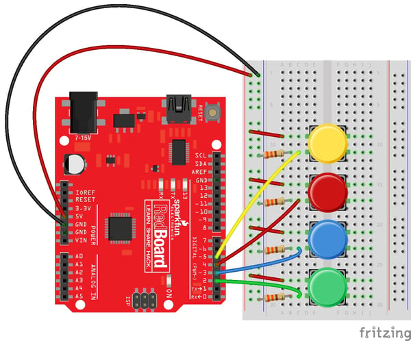
The first thing we should always do when starting an Arduino project is to jump power and ground pins on the RedBoard or other microcontroller to the '+' and '-' tracks on the breadboard. This allows your components to easily access power and ground from anywhere on the breadboard.
As you can see in the circuit diagram above, each button has two leads that we will be working with, which are located on the left side of the well in the breadboard. One of the leads for each button should connect directly to power, which is demonstrated with a red jumper wire in the diagram.
The second lead is treated a little differently. First, the second lead needs to jump to an individual GPIO pin. Here we have Green -> Pin 2, Blue -> Pin 3, Red -> Pin 4, and Yellow -> Pin 5. That same lead that goes to the individual GPIO pin also needs to connect to ground via a resistor. This acts as a 'pull down resistor,' which is a resistor we use to help get a clean 'LOW' reading when the button is not pressed.
The Code
Now that we've built our circuit it's time to write and upload our program. I have provided example code below with comments to demonstrate the function of each line.
//Vote Counter for by Melissa Felderman for SparkFun Electronics
//declaring the digital IO pin value for each button
int greenBut = 2;
int blueBut = 3;
int redBut = 4;
int yellowBut = 5;
//variable to hold button reading
int greenVal;
int blueVal;
int redVal;
int yellowVal;
//variable to hold the total vote count
int greenTotal = 0;
int blueTotal = 0;
int redTotal = 0;
int yellowTotal = 0;
//variables used in debounce functions to make sure on press = one vote
bool greenBool = false;
bool blueBool = false;
bool redBool = false;
bool yellowBool = false;
unsigned long lastDebounceTime = 0;
unsigned long debounceDelay = 200;
void setup() {
//initiate the serial moniter
Serial.begin(9600);
//let Arduino know that the digital pins are recieveing input
pinMode(greenBut, INPUT);
pinMode(blueBut, INPUT);
pinMode(redBut, INPUT);
pinMode(yellowBut, INPUT);
}
void loop() {
//read the value of the buttons and store them in a variable
greenVal = digitalRead(greenBut);
blueVal = digitalRead(blueBut);
redVal = digitalRead(redBut);
yellowVal = digitalRead(yellowBut);
//if statements below allow us to press the button and get several HIGH readings with one press, but only register one vote per press
if ((millis() - lastDebounceTime) > debounceDelay) {
if ((greenVal == HIGH) && (greenBool == false)) {
greenBool = true;
greenTotal++;
Serial.write(0);
lastDebounceTime = millis();
} greenBool = false;
if ((blueVal == HIGH) && (blueBool == false)) {
blueBool = true;
blueTotal++;
Serial.write(1);
lastDebounceTime = millis();
} blueBool = false;
if ((redVal == HIGH) && (redBool == false)) {
redBool = true;
redTotal++;
Serial.write(2);
lastDebounceTime = millis();
} redBool = false;
if ((yellowVal == HIGH) && (yellowBool == false)) {
yellowBool = true;
yellowTotal++;
Serial.write(3);
lastDebounceTime = millis();
} yellowBool = false;
}
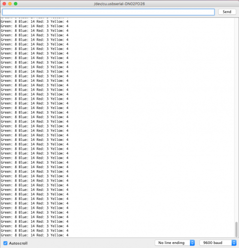
//serial print commands to show results in the serial monitor
Serial.print("Green: ");
Serial.print(greenTotal);
Serial.print(" ");
Serial.print("Blue: ");
Serial.print(blueTotal);
Serial.print(" ");
Serial.print("Red: ");
Serial.print(redTotal);
Serial.print(" ");
Serial.print("Yellow: ");
Serial.println(yellowTotal);
}Once you have uploaded the program, you can open our serial monitor in Arduino and see the vote counts in real time!
Let us know what you think about this classroom project in the comments below!
SIK