
Last time, we dove under the hood of the Arduino UNO and looked at how registers work in microcontrollers. While the Arduino framework is a great tool for making projects quickly and with little effort, learning the inner workings is a great experience for anyone looking to take their understanding of microcontrollers to the next level.
Interrupts are crucial to the operation and function of most modern microcontrollers. They allow you to pause whatever the processor was working on, execute some other piece of code, and then go back to its main function. This is useful for things like responding to button presses instantaneously, polling a sensor at exact intervals, or controlling the speed of a motor using precisely timed pulses (pulse width modulation). In the following two videos, I will show you how external and timer interrupts work in the AVR ATmega328P and how to set them up using the Arduino framework.
Any time you want to set up an interrupt, you need to make sure the following three things happen in order for the interrupt to trigger:
- Global interrupts must be enabled (in AVR, this is accomplished with the
sei()function). Note that global interrupts are enabled by default in Arduino. - The individual interrupt must be enabled (usually by setting a bit in a particular register associated with that interrupt).
- The interrupt condition must be met (e.g., a falling edge on a particular pin).
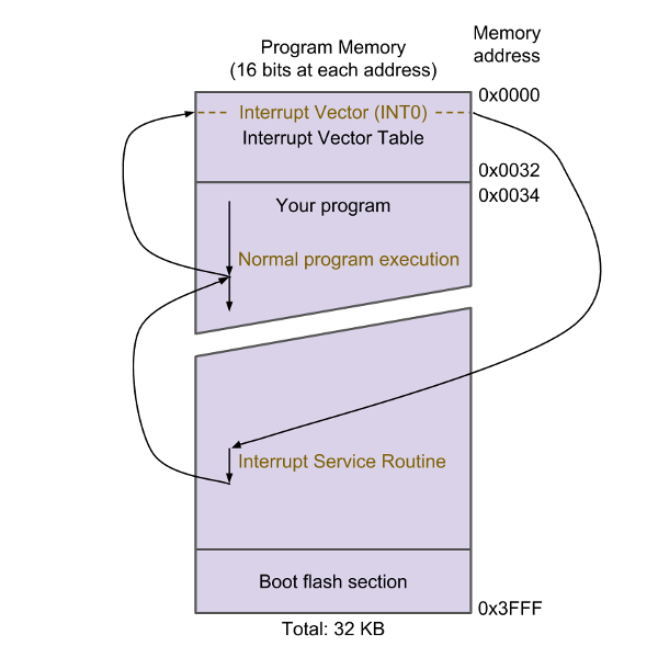
If all three conditions are met, the interrupt will happen. The processor will stop executing its main program, state variables will be saved to memory, and execution will jump to the interrupt vector table (IVT). The IVT tells the processor where to go next depending on which interrupt occurred (this is known as an"interrupt vector"). An external interrupt that occurs on Port D Pin 2 (PD2) is known by the label INT0.
The IVT resides at the top of program memory. The processor jumps to the INT0 address, which usually contains a single instruction that tells the processor to jump again to somewhere else in memory. This next location contains the interrupt service routine (ISR), which can contain any number of instructions for the processor to execute next. Once it has finished executing the ISR, the processor then jumps back to wherever it left off in the main program.
To avoid having your processor sit in the ISR for long periods of time (and avoid missing crucial calculations or other interrupts), it is advised that ISRs be as short as possible.
When it comes to timers, the ATmega328P has three timers that you can work with. These can be used to trigger an ISR at various intervals (sample a sensor, calculate a new value, etc.) or toggle/set a pin without needing to call an ISR (useful for setting up fire-and-forget pulse width modulation).
| Name | Size | Possible Interrupts | Uses in Arduino |
|---|---|---|---|
| Timer0 | 8 bits (0 - 255) |
Compare Match Overflow |
delay(), millis(), micros() analogWrite() pins 5, 6 |
| Timer1 | 16 bits (0 - 65,535) |
Compare Match Overflow Input Capture |
Servo functions analogWrite() pins 9, 10 |
| Timer2 | 8 bits (0 - 255) |
Compare Match Overflow |
tone() analogWrite() pins 3, 11 |
Note that each of these timers can be configured to trigger one or more interrupts:
- Compare Match — When the timer value reaches a specific value (stored in the corresponding output compare register), an interrupt will be generated. This can be useful for creating pulse width modulation (PWM) signals on pins or sampling a sensor at specific intervals.
- Overflow — When the timer rolls over from its max value (e.g., 65,535) to 0, an interrupt is generated. Overflow interrupts are also used for PWM signals and running pieces of code at precise intervals.
- Input Capture — When a specific pin changes value (e.g., ICP1), the current timer value is stored in another register (ICR1) that can be retrieved later to see the exact time that event occurred. This type of interrupt is good for measuring the time between pulses.
Interrupts are incredibly powerful tools for making microcontrollers respond quickly to input or meeting strict timing requirements. Specifically, the hardware interrupts that we see in many microcontrollers are an important factor that sets them apart from microprocessors (e.g., the main CPU on the Raspberry Pi).
The Arduino framework does allow us to use interrupts, but they're often obscured behind other functions, like analogWrite(), attachInterrupt(), or tone(). Understanding how to manually configure interrupts with registers can open up more advanced features on a microcontroller. However, note that if you move to another architecture (e.g., ARM), you will need to learn a whole new set of registers and interrupt configuration procedures.

Arduino, programming, computer science