As we dig into the world of electronics, one of the first questions to arise is "How do I test this?" Let’s take a look at some common test procedures and tools. In my world, testing takes one of two possible courses: either software or hardware and instrumentation, including use of a multimeter, oscilloscope and logic analyzer.
Software Troubleshooting
In software, I tend to use two things to confirm a condition: the first is a simple LED turning off or on to signal if I have reached a certain point in a program. I tend to resort to turning LEDs on or off for threshold values in a sensor reading; I use them to confirm that serial data has been sent or received; and I use them to check program flow in switch cases and conditional logic statements.
The other option that is a “go to” for me is a serial print statement. The serial print statement is a basic troubleshooting technique that seems to be overlooked with surprising regularity. It consists of a few simple lines of code in Arduino:
void setup() {
// initialize serial:
Serial.begin(9600);
}
void loop(){
Serial.println(data)
}
(“println()” in Processing) can confirm or deny the presence of data and the value of the data, map program flow and troubleshoot connections and timing in all kinds of systems.
It also allows input to simulate communication between systems like a laptop and an Arduino. An example of this is to enter data from a terminal in Arduino and have the Arduino parse the incoming data and respond to it. My favorite “first try” of this is in the Arduino examples under: file>examples>communication>readASCIIString.
Hardware Troubleshooting
The next set of tools are actual physical tools, some of which may be very familiar to you for measuring electrical signals. The three we’ll discuss are the multimeter, the oscilloscope and the logic analyzer.
The Multimeter
The multimeter is ubiquitous in shops and labs using electrical and electronics in any way. The most common functions used on “the meter” are testing for voltage, testing for current, testing for resistance and testing for continuity. For a “how to” on using a multimeter, we’ve created a video that will walk you through using one.
The Oscilloscope
The next level of measurement equipment is the oscilloscope, which measures the presence of voltage, but at extremely fast speeds in order to get a window into data streams, pulsed signals and voltage behavior at times in the millisecond and microsecond range.
And I’ll point to another fine SparkFun video:
Logic Analyzer
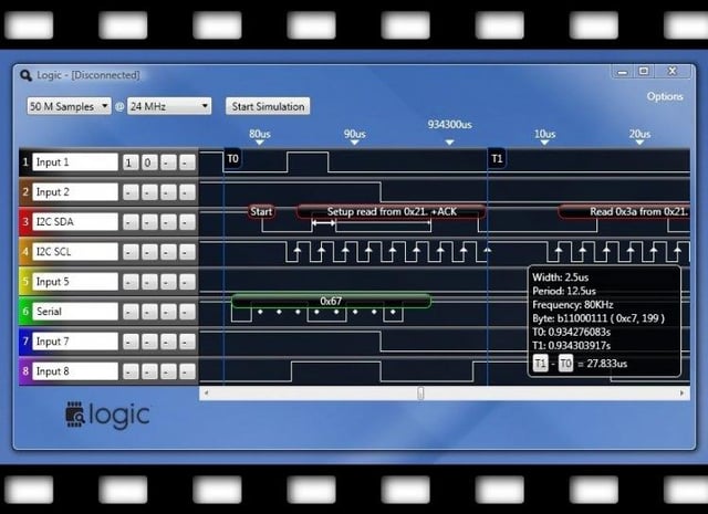
Our last tool is the logic analyzer. Much like the oscilloscope, it measures the amplitude and duration of an electrical signal, but its strength is to record and help translate these trains of pulses in the way the computer sees them.
My favorite analyzer is the Saleae Logic 4.

The Logic 4 plugs into a USB port, and the software is free, easy to use and remarkably simple. For troubleshooting and exploring serial data, I2C, SPI and virtually all forms of communication between computers and microcontrollers, it’s my best friend. It’s a bit of a time investment to get to know the analyzer, but well worth it for such a rewarding process.
By and large I use the meter, scope and analyzer for hardware-specific problems and software for program flow and variable troubleshooting. There is no hard and fast set of rules, but you’ll find it becomes a creative skillset with a little practice.
Feel free to post specific questions and share your tools and techniques below. Happy signal hunting!


Arduino, teaching tools, Maker Education, Processing, getting started, programming